How Tight Tolerances Can Your Singapore CNC Machining Shop Hold? (Micron-Level Guide)
In high‑precision industries—from aerospace to automotive—the ability to hold ultra‑tight tolerances differentiates functional parts from failures. For engineers, purchasers, and decision‑makers evaluating Custom CNC Machining Services in Singapore, understanding micron‑level capabilities is crucial. This guide dives deep into tolerance standards, factors that influence precision, and real‑world benchmarks across sectors, ensuring you choose a partner who can deliver parts that meet or exceed your requirements.
Why Tolerance Matters in CNC Machining
Tolerances define the allowable variation in a part’s dimensions. When parts must mate with other components—whether turbine disks in aircraft engines or transmission gears in cars—even a few microns of deviation can lead to reduced performance, premature wear, or catastrophic failure.
- Fit & Function: Precise tolerances ensure seamless assembly without shims or rework.
- Performance: Aerodynamic surfaces, bearing journals, and optical mounts all demand tight profiles for optimal operation.
- Reliability: Consistent tolerances reduce variability, improving lifecycle and maintenance intervals.
By selecting Custom CNC Machining Services that guarantee micron‑level control, you protect product integrity and brand reputation.
Micron‑Level Tolerance Categories
Tolerance capability depends on machine type, material, geometry, and inspection methods. Below is a general breakdown:
| Tolerance Class | Range | Typical Applications |
|---|---|---|
| General‑Purpose | ±0.05–0.10 mm (50–100 µm) | Brackets, fixtures, simple enclosures |
| Precision Machining | ±0.01–0.03 mm (10–30 µm) | Hydraulic valves, servo housings |
| Ultra‑Precision | ±0.005–0.01 mm (5–10 µm) | Aerospace impellers, medical implants |
| Sub‑Micron (Specialist) | ±0.001–0.005 mm (1–5 µm) | Optical components, specialized sensors |
Different sectors demand different tolerance classes; understanding these categories will help you specify the right requirements when sourcing Custom CNC Machining Services.
Standard Tolerances in Manufacturing: ISO 2768, ISO 286, and GD&T
Choosing the right tolerances is crucial for any engineering project as it affects the component’s functionality, manufacturability, lead time, and cost. This article will explore the key tolerance standards used in subtractive manufacturing, specifically ISO 2768, ISO 286, and Geometric Dimensioning and Tolerancing (GD&T), providing guidance on when and how to apply these standards to ensure optimal performance and efficiency in your engineering designs.
Tolerances define the permissible limits of variation in a physical dimension, ensuring that the features of a part are produced within acceptable limits for its intended application.
In practice, specifying tolerances for every feature of a component can be time-consuming and inefficient. To streamline this process, designers and engineers often use standardized tolerance values defined by international standards, such as those set by the International Organization for Standardization (ISO). These standards provide general tolerances that apply by default, reducing the need to calculate specific tolerances for every feature.
ISO Tolerance Standards
In Europe and many other parts of the world, general tolerances for subtractive manufacturing (such as CNC machining) are primarily defined by two key ISO standards: ISO 2768 and ISO 286.
- ISO 2768 provides general tolerances for linear and angular dimensions when specific tolerances are not indicated on the engineering drawing. This standard is typically used for features like external sizes, internal sizes, diameters, distances, chamfer heights, and radii, where default tolerance ranges are sufficient for the part’s function.
- ISO 286, on the other hand, specifically applies to tolerances for cylindrical surfaces and distances between parallel plane surfaces, such as those found in shaft and hole systems. It is intended for situations where precise fits are necessary between mating parts. ISO 286 should be applied when these specific types of features are present, and the tolerances need to be more tightly controlled than what is provided by the general tolerance standards.

By default, all tolerances should conform to ISO 2768 unless a more precise tolerance is required for specific features, in which case this must be explicitly indicated on the drawing using the appropriate ISO standard, such as ISO 286. This approach ensures clarity in the manufacturing process and helps maintain quality and consistency across parts.Tolerance stack up question
Standard Tolerances at CNC MACHINING PTE. LTD
At CNC MACHINING PTE. LTD, we provide a range of standardized tolerance options to accommodate various manufacturing needs:
- ISO 2768 – Fine
- ISO 2768 – Medium
- ISO 286 – Grade 6
- ISO 286 – Grade 7
- ISO 286 – Grade 8
The table below gives a concise summary of these tolerance standards.

How to Choose the Right Tolerance
Selecting the appropriate tolerance is a critical decision in the design and manufacturing process, since it affects the functionality, fit, cost, and manufacturability of the part. The right tolerance ensures that parts fit together as intended and function correctly in their operating environment, without unnecessary cost or manufacturing complexity.
The table below provides a guide to common use cases, describing the recommended tolerance standards (ISO 2768 and ISO 286) based on the specific requirements and functionalities of different parts.
| Application | Description | Recommended tolerance standard | Reason for tolerance choice |
|---|---|---|---|
| Precision machined parts | High-precision components used in aerospace, automotive, or medical devices where exact fit is critical. | ISO 2768 Fine and ISO 286 Grade 6 (IT6) or higher | Ensures minimal variation for linear and angular dimensions (ISO 2768) and tight control for cylindrical fits (ISO 286). |
| Interchangeable mechanical parts | Parts designed to be easily replaced or exchanged, like gears, bearings, and fasteners in assemblies. | ISO 2768 Fine and ISO 286 Grade 7 (IT7) or higher | Allows for precise linear/angular fits (ISO 2768) and standardized fits for shafts and holes (ISO 286). |
| General mechanical assemblies | Components in general machinery that require good fits but not ultra-high precision, like housings or brackets. | ISO 2768 Medium | Provides a balance between precision and manufacturability for linear and angular dimensions. |
| Large fabricated structures | Parts used in construction or heavy machinery where exact fits are less critical, such as beams or plates. | ISO 2768 Medium | Tolerances accommodate larger dimensions and processes like welding or fabrication. |
| Plastic components | Molded or machined plastic parts for consumer products or electronics, where some dimensional variability is acceptable. | ISO 2768 Medium and ISO 286 Grade 8 (IT8) or higher | Tolerances consider material flexibility (ISO 2768) and accommodate standard fits (ISO 286) for plastics. |
| Shafts and holes for rotating components | Components like shafts and holes in rotating machinery that require specific fits to ensure proper function. | ISO 2768 Fine and ISO 286 Grades 6 or 7 (IT6, IT7) | Ensures precise linear/angular dimensions (ISO 2768) and tight fits for rotational balance (ISO 286). |
| Sheet metal parts | Parts made from sheet metal for enclosures, panels, and brackets where tight fits are not critical. | ISO 2768 Medium | Tolerances are suitable for processes like bending and forming, accommodating inherent variabilities. |
| Electrical enclosures and casings | Enclosures for electrical components that must fit together but do not require tight tolerances. | ISO 2768 Medium | Provides sufficient accuracy for assembly while reducing costs for non-precision parts. |
| Consumer product components | Parts in consumer electronics or appliances where aesthetic finish and function are prioritized over tight tolerances. | ISO 2768 Medium and ISO 286 Grade 8 (IT8) | Balances manufacturing efficiency with adequate fit and function, using standard tolerances for general fits. |
Practical Guidelines for Choosing Tolerances
- Start with general tolerances (ISO 2768): Use ISO 2768 (Fine or Medium) for general-purpose parts unless specific tolerance requirements are defined.
- Specify tighter tolerances (ISO 286): For features involving precise fits or where high manufacturing accuracy is essential (e.g., shafts, holes), use ISO 286. Choose the grade (6, 7, or 8) based on the desired level of precision and fit.
- Balance precision with cost: Always aim to choose the loosest tolerance that still meets the part’s functional requirements to optimize cost-efficiency.
- Document specific requirements clearly: If a feature requires a specific tolerance beyond the general standard, ensure it is clearly indicated on the engineering drawing to avoid manufacturing errors.
ISO 2768 Tolerances
ISO 2768 is a widely used standard that defines general tolerances for parts manufactured through machining or other material removal processes. It provides a framework for achieving acceptable precision without specifying individual tolerances, simplifying design and manufacturing when high precision isn’t needed for every dimension.
ISO 2768 applies specifically to drawings that do not have custom tolerance specifications for the following features:
- Linear dimensions: Includes external and internal sizes, diameters, distances, chamfer heights, and radii.
- Angular dimensions: Covers angular measurements where specific tolerances are not indicated.
- Dimensions of machined and assembled parts: Applicable to both linear and angular dimensions produced during the machining of assembled components.
Tolerances for Linear Dimensions
The table below outlines the ISO 2768 tolerance limits for linear dimensions across different nominal size ranges, categorized into Fine (f) and Medium (m) tolerance classes.

How to read the table: For a part with a nominal dimension range of 50 mm, under the Fine (f) tolerance class, the acceptable deviation would be ±0.15 mm.
Tolerances for External Radius and Chamfer Heights
The table below shows the ISO 2768 standard tolerances for external radii and chamfer heights, categorized by Fine (f) and Medium (m) tolerance classes. These tolerances define permissible deviations for curved surfaces and chamfered edges.

How to read the table: For an external radius of 4 mm, the applicable nominal dimension range is ‘over 3 to 6 mm.’ If you select the Fine (f) tolerance class, the acceptable deviation would be ±0.5 mm.
Tolerances for Angular Dimensions
The table below details the ISO 2768 tolerances for angular dimensions, expressed in degrees and minutes. These tolerances apply to the shorter leg of an angle and are categorized by Fine (f) and Medium (m) tolerance classes.

How to read the table: For an angular measurement with a nominal dimension range of 30 mm, under the Fine (f) tolerance class, the acceptable deviation would be ±0°30′.
ISO 286 Tolerances
ISO 286 is a standard commonly applied to subtractive manufacturing methods, such as CNC machining, to define tolerances for linear dimensions of specific features. It is particularly relevant for parts that include:
- Cylindrical features: Such as shafts and holes where precise fits are essential.
- Two parallel opposite surfaces: Like those found in mating parts or assemblies, requiring a controlled distance between them.
This standard is used for features on engineering drawings where specific tolerances are not individually indicated.
ISO 286 Quality Grades
The ISO 286 provides a standardized selection of tolerance classes for general purposes from amongst the numerous possibilities. It is also possible to specify dimensions with higher a grade, they will be automatically integrated into our price calculations (for parts to be produced in CNC machining). At CNC MACHINING PTE. LTD, we offer three quality grades under the ISO 286 standard:
- Grade 6 (IT6): For very tight tolerances, used in high-precision applications where minimal deviation is critical.
- Grade 7 (IT7): For general engineering applications requiring a balance between precision and manufacturability.
- Grade 8 (IT8): For less critical applications where a looser fit is acceptable, reducing manufacturing complexity and cost.
Keep in mind that tolerance limits can also be customized outside the ISO 286 grade system. When you do this, CNC MACHINING PTE. LTD will convert your specified tolerances to the nearest equivalent ISO 286 grade for internal processing. For instance, if you specify a tolerance of ’50 +0.05/+0.02′ for the distance between two parallel surfaces, we’ll calculate the tolerance range as 30µm, which aligns most closely with grade 7 in the ISO 286 standard.
Key Terms in ISO 286 Tolerances
Understanding ISO 286 tolerances involves knowing a few key terms:
- Nominal size: The specified size of a feature as indicated on the engineering drawing.
- Actual size: The measured size of a feature after manufacturing.
- Upper limit of size: The maximum permissible size of a feature.
- Lower limit of size: The minimum permissible size of a feature.
- Tolerance: The difference between the upper and lower limits of size, defining the allowable tolerance range.
ISO 286 Tolerances for Linear Dimensions
The table below provides the ISO 286 tolerance limits for linear dimensions based on different nominal dimension ranges, presented in micrometers (µm) for three quality grades: IT6, IT7, and IT8.

How to read the table: For a feature with a nominal dimension range between 50 mm and 80 mm, using ISO 286 Grade IT6, the acceptable tolerance would be ±19 µm.
Geometric Dimensioning and Tolerancing (GD&T)
GD&T is a precise system for defining and communicating engineering tolerances, providing control over the geometry of part features. Unlike linear tolerances, which only address size, GD&T focuses on the geometric relationships between features, ensuring that parts function properly within an assembly. This method is critical when accurate fit, form, and function are required, particularly in complex assemblies such as those found in the aerospace, automotive, and medical industries.eBook: Mastering Tolerances for Machined Parts
GD&T is governed by standards like ISO 1101 – Geometric Product Specifications (GPS) and ASME Y14.5, and it encompasses four major categories of tolerances:
- Form Tolerances: Control individual feature shapes such as flatness, straightness, roundness, and cylindricity.
- Orientation Tolerances: Govern the angular relationship between features, such as perpendicularity, parallelism, and angularity.
- Location Tolerances: Define the exact position of features like holes or slots, ensuring the proper alignment and spacing of components.
- Runout Tolerances: Control the movement of rotating parts, ensuring that features remain aligned and free from wobble or eccentricity during operation.
Each tolerance category enables engineers to ensure that parts will fit together precisely and perform correctly under specific conditions. For example, a tight perpendicularity tolerance may be required to ensure that a shaft is properly aligned with a housing or a position tolerance might be needed to ensure that a hole is located exactly where it needs to be for assembly.

Should I use gd&t or traditional linear dimensions for tight tolerances on motor mount bracket?
Applying GD&T allows for tighter control over critical part features, leading to higher product quality and better performance. However, this also increases the complexity of the design and verification process. It is important to avoid over-tolerancing, as applying unnecessarily tight geometric tolerances can significantly raise manufacturing costs and extend lead times. The use of GD&T should be limited to features that directly affect part performance in the assembly, known as “critical-to-function” features.
Verifying GD&T tolerances requires sophisticated measurement equipment, such as Coordinate Measuring Machines (CMMs), laser scanners, or optical comparators, to accurately measure and validate these geometric relationships. These tools are essential for confirming that parts conform to their specified tolerances, especially when dealing with extremely tight tolerances for form and location.
ISO vs. ASME Tolerance Standards
ISO standards, such as ISO 2768 and ISO 286, are widely used in Europe, the UK, Turkey, and parts of Asia, focusing on general tolerances and fits for a broad range of applications. In contrast, ASME standards, like ASME B4.1 and ASME Y14.5, are more prevalent in the United States and offer detailed guidelines, especially for geometric dimensioning and tolerancing (GD&T).
The table below compares these standards and highlights their equivalents, offering a quick reference for selecting the appropriate standards based on regional practices and specific manufacturing needs.
| ISO Standard | Equivalent ASME Standard | Application | Key Difference |
|---|---|---|---|
| ISO 2768 (Fine, Medium) | ASME Y14.5 | General tolerances for linear and angular dimensions | ISO 2768 provides general tolerances, while ASME Y14.5 offers detailed geometric dimensioning guidelines (GD&T). |
| ISO 286 (Grade 6, 7, 8) | ASME B4.1 (Grade 6, 7, 8) | Tolerances for cylindrical fits and distances between parallel surfaces | Both standards define similar tolerance grades for fits, but ASME includes additional guidance specific to US practices. |
| ISO 2768 for Angular Dimensions | ASME B4.2 | Angular dimension tolerances | Similar angular tolerance ranges, but ASME B4.2 may offer more detailed instructions for specific applications. |
| ISO 1101 (Geometric Tolerancing) | ASME Y14.5 (GD&T) | Geometric tolerancing of shapes and features | Both provide frameworks for GD&T, but ASME Y14.5 is more detailed and widely used in the US. |
Sector Benchmarks for CNC Tolerances
Aerospace CNC Tolerance Standards
- Critical Structural Parts (wing fittings, bulkheads): ±0.01 mm (10 µm)
- Rotating Components (impellers, turbine disks): ±0.005 mm (5 µm)
- Sensor & Optical Housings: ±0.002 mm (2 µm)
Aerospace parts often require simultaneous 5‑axis CNC machining to maintain multi‑surface geometric tolerances (GD&T) in a single setup, minimizing misalignment.
Automotive CNC Tolerances in Singapore
- Engine Components (cams, crankshafts): ±0.01–0.02 mm (10–20 µm)
- Transmission Gears & Splines: ±0.005 mm (5 µm) for high‑performance applications
- Sensor Mounts & Electronic Housings: ±0.02–0.05 mm (20–50 µm)
High‑volume automotive runs often balance cost and precision. Advanced shops offering 5‑axis precision machining tolerances can achieve tighter specs with fewer setups, reducing per‑part cost.
Medical Device Tolerance Requirements
- Implants (spinal, orthopedic screws): ±0.005 mm (5 µm)
- Surgical Instruments: ±0.01 mm (10 µm)
- Diagnostic Equipment Parts: ±0.002 mm (2 µm)
Medical-grade CNC parts must also adhere to surface finish standards (e.g., Ra 0.2 µm) and biocompatibility traceability, adding layers to tolerance control.
Factors Influencing Tolerance Capability
Machine & Tooling Precision
- 5‑Axis CNC Machining Singapore centers equipped with high‑rigidity spindles and linear motors maintain positional accuracy to ±1 µm.
- Spindle Runout: Premium bearings and balance reduce wobble to under 2 µm.
- Toolholder & Collet System: High‑precision toolholders (HSK‑A or CAT‑40) ensure sub‑3 µm tool runout.
Material Properties
- Thermal Expansion: Aluminum alloys may expand 23 µm per meter per °C, so temperature‑controlled environments are vital for ±5 µm tolerances.
- Stress Relief: Pre‑machining heat treatment or stress relieving minimizes warping in stainless steels and titanium.
H3: Fixturing & Workholding
- Modular Tombstones & V-blocks: Provide repeatable clamping within ±2 µm.
- Pneumatic/Vacuum Fixtures: Ideal for thin‑walled or delicate parts, reducing deformation.
CAM Strategy & Toolpath Optimization
- Adaptive Clearing: Maintains constant tool engagement to reduce deflection.
- High‑Speed Machining (HSM): Lowers cutting forces, improving surface finish and dimensional accuracy.
- Micron Tolerance CNC Machining Software: CAM systems with collision detection and dynamic feed‑rate control.
Inspection & Quality Assurance
Metrology Equipment
- Coordinate Measuring Machines (CMM): Bridge and gantry CMMs verify dimensions down to 1 µm.
- Vision Systems & Optical Comparators: Measure small features and detect deviations quickly.
- Surface Profilometers: Ensure surface roughness meets both functional and tolerance specs.
Process Controls
- Statistical Process Control (SPC): Tracks key dimensions in real time, preventing drift.
- First Article Inspection (FAI): Validates initial parts before full production.
- In‑Process Probing: On‑machine probes check critical features mid‑cycle, triggering tool replacements if wear exceeds tolerance thresholds.
Achieving Ultra‑Tight Tolerances with Custom CNC Machining Services
To secure micron‑level precision for your next project:
- Specify Your Tolerance Goals Early
- Clearly define tolerance zones and GD&T callouts on your drawings.
- Choose the Right Material & Treatment
- Match material properties to functional requirements; include stress‑relief processes if needed.
- Partner with a Certified Shop
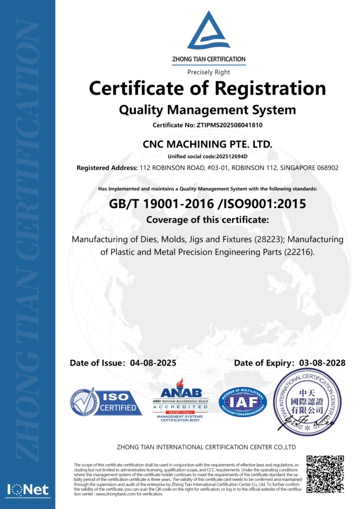
- Look for ISO 9001:2015, AS9100D, or IATF 16949 accreditation in Singapore CNC machining shops.
- Embrace Digital Twin & Simulation
- Virtual toolpath verification can identify potential tolerance issues before cutting steel.
- Invest in Advanced Inspection
- Utilize CMM, in‑process probing, and SPC dashboards for ongoing assurance.
By following these steps, you’ll maximize the chance of parts exiting the shop floor within ±0.005 mm reliably—critical for aerospace jets, automotive transmissions, and medical implants.
Conclusion
When evaluating Custom CNC Machining Services in Singapore, micron‑level tolerance capability is a key differentiator. Whether your project demands ±50 µm for general‑purpose components, ±10 µm for hydraulic manifolds, or sub‑5 µm for flight‑critical or life‑saving devices, understanding the factors that influence precision ensures you select the right machining partner. Armed with this guide, procurement leaders, engineers, and decision‑makers can confidently specify tolerance requirements and leverage Singapore’s advanced CNC industry to deliver parts that perform flawlessly in the most demanding environments.